

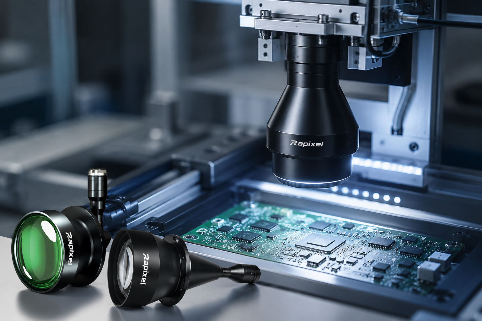
Telecentric Lens for AOI: A Practical Guide to Precision Optical Inspection
Learn how telecentric lenses improve AOI imaging with stable magnification, reduced perspective effects, and consistent image geometry for precision inspection.
Why Use a Telecentric Lens for AOI?
A telecentric lens for AOI is designed to maintain highly stable magnification over a defined object-space range while reducing perspective-related changes in image size. This makes telecentric imaging particularly useful for automated optical inspection applications that require repeatable edge detection, dimensional inspection, and consistent object geometry.
Automated Optical Inspection (AOI) systems are often associated with high-resolution cameras and advanced inspection software. However, the optical system in front of the camera can be just as important as the camera itself.
When AOI involves small electronic components, precision mechanical parts, connectors, PCB features, or dimensional inspection, conventional imaging may introduce perspective-related changes that affect image consistency.
A telecentric lens can help reduce these effects by maintaining stable magnification within its specified operating range. When combined with an appropriate camera and controlled illumination, telecentric imaging can provide a more repeatable foundation for AOI inspection.
In This Guide
- Why Does AOI Need Telecentric Imaging?
- Key Benefits of Telecentric Lenses for AOI
- Where Are Telecentric Lenses Used in AOI?
- Telecentric Lens + High-Resolution Camera
- Why Lighting Matters in AOI
- Telecentric Lens + Telecentric Light
- 90° Telecentric Lens + 90° Telecentric Light for AOI
- Applications for 90° Telecentric Imaging
- How to Choose a Telecentric Lens for AOI
- Building a Complete Telecentric AOI System
- Frequently Asked Questions
1. Why Does AOI Need Telecentric Imaging?
AOI systems are designed to inspect products consistently at production speed. Depending on the application, the system may need to identify defects, measure dimensions, locate components, inspect edges, or verify assembly quality.
These tasks depend on the quality and consistency of the captured image. With a conventional lens, changes in object position can cause perspective-related changes in apparent size.
Small Height Variations
PCB flatness, component height, or positioning can vary during inspection.
Perspective Effects
Apparent object size can change as the distance between the object and lens changes.
Measurement Variation
Changes in image geometry can affect dimensional inspection and edge detection.
Telecentric imaging addresses this challenge by reducing perspective-related magnification changes within the specified telecentric object-space range.
2. Key Benefits of Telecentric Lenses for AOI
Stable Magnification
Helps maintain consistent object size when object position changes within the specified operating range.
Reduced Perspective Effects
Reduces perspective-related variation in image geometry.
Repeatable Edge Imaging
Provides more consistent representation of edges, holes, pins, and component boundaries.
Precision Measurement
Supports dimensional inspection where geometric consistency is important.
3. Where Are Telecentric Lenses Used in AOI?
Telecentric lenses are particularly useful in AOI applications where image geometry and measurement repeatability are important.
PCB Inspection
Component placement, PCB features, holes, connectors, and dimensional inspection.
Electronic Components
IC packages, terminals, pins, connectors, and small electronic assemblies.
Semiconductor Components
Precision inspection where stable imaging and high resolution are required.
Precision Mechanical Parts
Machined parts, pins, gears, holes, edges, and dimensional features.
4. Telecentric Lens + High-Resolution Camera for AOI
A high-resolution camera can capture more image detail, but camera resolution alone does not determine the final optical performance of an AOI system.
The camera and lens should be matched according to sensor size, pixel size, magnification, field of view, working distance, and optical resolution.
| System Component | Important Parameters |
|---|---|
| Camera | Sensor size, pixel size, resolution, frame rate, shutter type |
| Telecentric Lens | Magnification, FOV, working distance, resolution, distortion |
| Lighting | Contrast, uniformity, reflection control, illumination geometry |
5. Why Lighting Matters in AOI
Even the best telecentric lens cannot compensate for poor illumination. The inspection feature must be visible with sufficient contrast for the camera and vision algorithm to process it reliably.
Reflective Surfaces
Controlled lighting can help manage unwanted reflections from metal and electronic surfaces.
Edges and Holes
Appropriate illumination can improve silhouette and edge contrast.
Surface Features
Directional or diffuse illumination may be selected according to the defect or feature being inspected.
This is why telecentric imaging and illumination should be evaluated together rather than selecting the lens independently from the lighting system.
6. Telecentric Lens + Telecentric Light
For dimensional inspection and silhouette-based AOI, telecentric illumination can complement the optical geometry of a telecentric lens.
The exact lighting configuration depends on the object surface, feature being inspected, working distance, required contrast, and mechanical constraints.
7. 90° Telecentric Lens + 90° Telecentric Light for AOI
Some AOI systems face a challenge that cannot be solved simply by choosing a different magnification or working distance: limited installation space.
A conventional top-down imaging system places the camera and lens directly above the inspection object. However, machine structures, moving mechanisms, robots, cable routing, or limited vertical clearance may make this arrangement difficult to integrate.
The Space Constraint Problem
Straight Optical Path
Camera
↓
Telecentric Lens
↓
Inspection Object
Folded Optical Path
Camera
→
90° Turning Telecentric Lens
↓
Inspection Object
A 90° turning telecentric lens uses a folded optical path to change the physical direction between the camera and inspection object. This can provide greater flexibility when integrating telecentric imaging into compact AOI equipment.
Why Combine a 90° Telecentric Lens with a 90° Telecentric Light?
The lens determines how the object is imaged, while the illumination determines how the inspection feature is presented to the camera.
When the optical path is turned by 90°, the lighting arrangement should also be considered as part of the same system architecture.
Captures the inspection image.
Provides a folded telecentric optical path.
Measures and inspects the captured features.
8. Applications for 90° Telecentric Imaging
A 90° telecentric configuration can be considered when a conventional straight optical path is difficult to integrate into the machine.
PCB & Electronics AOI
Useful where machine structures or components limit vertical installation space.
Connector Inspection
Supports inspection of pins, terminals, edges, and connector geometry.
Precision Components
Suitable for dimensional and edge inspection where installation space is constrained.
Compact AOI Machines
Helps integrate imaging into equipment with limited vertical clearance.
9. How to Choose a Telecentric Lens for AOI
Selecting a telecentric lens for AOI should begin with the inspection requirement rather than the lens model.
Step 1 — Define the Object
Determine what product or component will be inspected.
Step 2 — Define the Inspection Feature
Identify whether the system needs defect detection, dimensional measurement, edge inspection, positioning, or another task.
Step 3 — Determine the Required FOV
Define the physical area that needs to be captured in one image.
Step 4 — Select the Camera
Consider sensor size, pixel size, resolution, frame rate, and interface.
Step 5 — Select the Telecentric Lens
Match magnification, FOV, working distance, sensor coverage, resolution, and distortion requirements.
Step 6 — Select the Lighting
Consider surface properties, contrast, reflection, and inspection geometry.
Step 7 — Check Mechanical Space
Confirm camera, lens, light, cable, and machine clearance. Consider a 90° optical configuration if a straight optical path is difficult to integrate.
10. Building a Complete Telecentric AOI System
For demanding AOI applications, the lens should be considered as part of a complete imaging system.
Image Acquisition
Resolution, sensor size, pixel size, frame rate, and shutter characteristics.
Optical Geometry
Magnification, FOV, WD, resolution, distortion, and telecentricity.
Feature Visibility
Contrast, reflection control, uniformity, and illumination geometry.
Inspection Processing
Measurement, pattern matching, defect detection, OCR, and positioning.
Telecentric Lens Solutions for AOI
Rapixel provides telecentric imaging solutions for precision inspection, AOI, dimensional measurement, electronics, semiconductor components, and other industrial vision applications.
Depending on the application, the optical configuration can include conventional telecentric lenses, high-resolution telecentric solutions, and specialized 90° turning telecentric designs.
Explore Rapixel Telecentric Lenses →Explore the Telecentric Lens Guide
Follow the complete guide from telecentric imaging fundamentals to AOI, lens selection, precision measurement, industrial applications, and complete vision system solutions.
Telecentric Lens Fundamentals
Understand telecentric imaging, perspective effects, magnification, and basic machine vision applications.
Explore Fundamentals →Telecentric Lens for AOI
Explore telecentric imaging for automated optical inspection, electronics, PCB, and precision component inspection.
You are hereTelecentric Lens Selection Guide
Learn how to select magnification, FOV, working distance, sensor compatibility, and optical performance.
Explore Selection Guides →Telecentric Lens for Precision Measurement
Discover dimensional measurement, edge inspection, and measurement repeatability using telecentric imaging.
Explore Measurement Guides →Telecentric Lens for Industrial Applications
Explore semiconductor, electronics, mechanical, plastic, battery, and precision manufacturing applications.
Explore Industry Applications →Telecentric Vision Systems & Solutions
Learn how cameras, telecentric lenses, lighting, and vision software work together in complete inspection systems.
Explore Vision Solutions →90° Telecentric Lens + 90° Telecentric Light for AOI
Take a closer look at the compact 90° optical configuration, including the space-constrained AOI challenge, optical path design, telecentric illumination, and practical inspection applications.
Explore the 90° AOI Solution →Frequently Asked Questions
What is a telecentric lens used for in AOI?
A telecentric lens is used in AOI when stable magnification, reduced perspective effects, repeatable edge representation, or dimensional consistency are important. Common applications include electronics, PCB, semiconductor, connector, and precision component inspection.
Why is telecentric imaging useful for PCB inspection?
Telecentric imaging can reduce perspective-related changes in magnification, helping maintain more consistent geometry when inspecting PCB features, components, connectors, holes, and other dimensional details.
Does every AOI system need a telecentric lens?
No. Standard machine vision lenses are suitable for many general inspection applications. Telecentric lenses are particularly useful when geometric consistency, dimensional measurement, or repeatable imaging is important.
What is a 90° turning telecentric lens?
A 90° turning telecentric lens uses a folded optical path to change the physical direction between the camera and inspection object. It can help integrate telecentric imaging into machines where a conventional straight optical path is difficult to install.
Why use a 90° telecentric light with a 90° telecentric lens?
Matching the illumination geometry with the optical configuration can help create a more compact and controlled AOI imaging system, especially when installation space is limited.
How do I choose a telecentric lens for AOI?
Start with the object size and inspection feature, then determine the required FOV, camera sensor size, magnification, working distance, resolution, distortion, lighting, and mechanical installation requirements.
Need Help Designing a Telecentric AOI System?
Share your object size, required FOV, camera sensor, working distance, inspection feature, available machine space, and lighting requirements. Rapixel can help evaluate a suitable telecentric imaging configuration.
Talk to a Vision Specialist →
Share:
Telecentric Lens Guide for Machine Vision
Why Need 90° Telecentric Lens & Light for AOI