

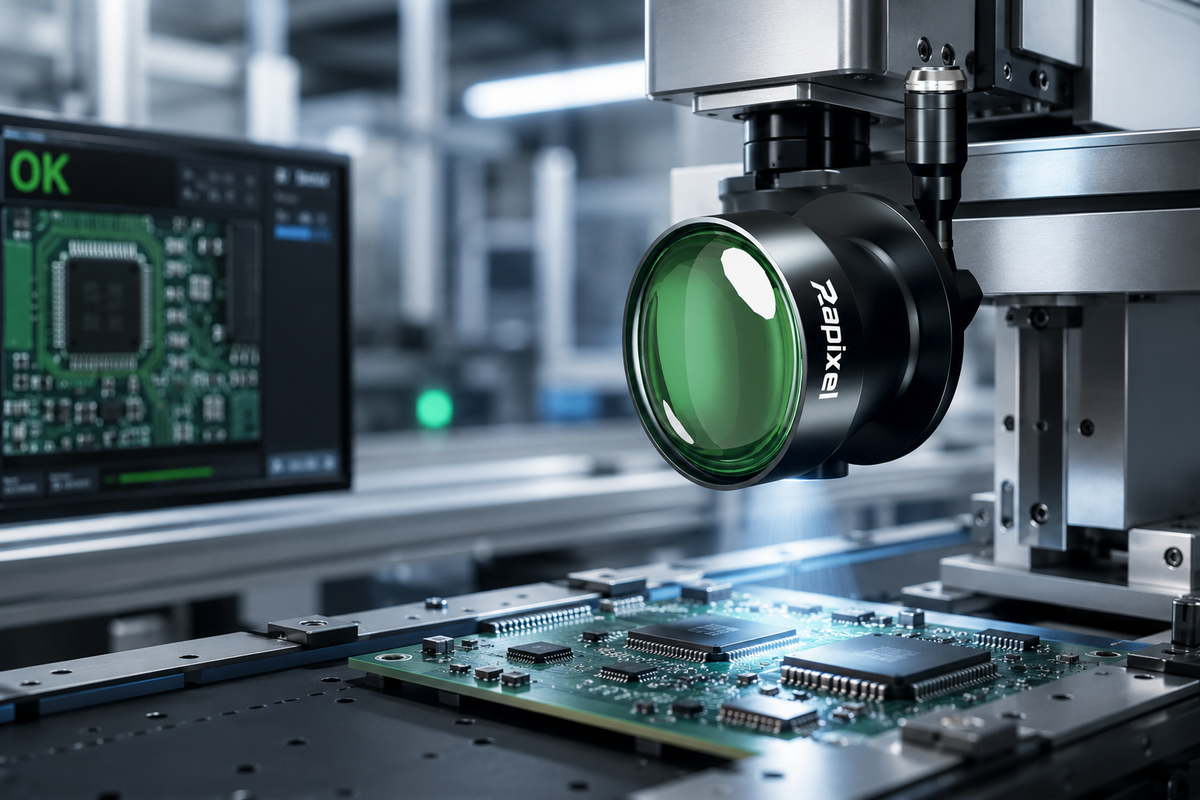
เลนส์เทเลเซ็นทริก 90° + แสงเทเลเซ็นทริก 90° สำหรับ AOI
คู่มือเชิงปฏิบัติสำหรับการถ่ายภาพเทเลเซ็นทริกแบบกะทัดรัดสำหรับการตรวจสอบแสงอัตโนมัติ (AOI) ที่จำกัดพื้นที่ โดยรวมเลนส์เทเลเซ็นทริกแบบหักเห 90° เข้ากับแสงสว่างแบบเทเลเซ็นทริกที่ควบคุมได้
ทำไมต้องใช้เลนส์เทเลเซ็นทริก 90° สำหรับ AOI?
A เลนส์เทเลเซ็นทริกแบบหักเห 90° ใช้เส้นทางแสงแบบพับเพื่ออนุญาตให้วางกล้องในตำแหน่งที่ห่างจากแกนมุมมองแบบดั้งเดิม ในขณะที่ยังคงรักษาการตั้งค่าการถ่ายภาพแบบเทเลเซ็นทริก เมื่อรวมกับแสงสว่างแบบเทเลเซ็นทริกที่ออกแบบมาอย่างเหมาะสม สามารถช่วยบูรณาการการถ่ายภาพ AOI ที่แม่นยำเข้ากับเครื่องจักรที่มีระยะห่างแนวตั้งจำกัดหรือการเข้าถึงทางแสงที่จำกัด
ระบบการตรวจสอบแสงอัตโนมัติ (AOI) กำลังกลายเป็นระบบที่กะทัดรัดมากขึ้น ในขณะที่ข้อกำหนดในการตรวจสอบยังคงเพิ่มขึ้น ในหลายแอปพลิเคชัน ประสิทธิภาพทางแสงเป็นเพียงส่วนหนึ่งของความท้าทาย พื้นที่ทางกายภาพที่มีให้สำหรับกล้อง เลนส์ และแสงสว่างอาจมีความสำคัญไม่แพ้กัน
ระบบการถ่ายภาพแบบเทเลเซ็นทริกแบบดั้งเดิมมักวางกล้องและเลนส์ไว้เหนือวัตถุที่ต้องการตรวจสอบโดยตรง การตั้งค่านี้ทำงานได้ดีเมื่อมีระยะห่างแนวตั้งเพียงพอ อย่างไรก็ตาม อุปกรณ์การผลิตอาจมีหุ่นยนต์ กลไกหยิบและวาง สายพาน ตัวจับยึด แอคชูเอเตอร์ หรือโครงสร้างอื่นๆ ที่ทำให้เส้นทางแสงตรงเป็นเรื่องยากที่จะบูรณาการ
A เลนส์เทเลเซ็นทริกแบบหักเห 90° ให้ทางเลือกหนึ่งโดยพับเส้นทางแสง เมื่อรวมกับ แสงเทเลเซ็นทริก 90°ที่เหมาะสม ระบบสามารถออกแบบรอบประสิทธิภาพทางแสงและข้อจำกัดทางกลไกได้
ในคู่มือนี้
- เลนส์เทเลเซ็นทริก 90° คืออะไร?
- ทำไม AOI ถึงต้องการการตั้งค่าทางแสง 90°?
- ทำไมไม่ใช้กระจกเพียงอย่างเดียว?
- ทำไมต้องรวมเลนส์เทเลเซ็นทริก 90° เข้ากับแสงเทเลเซ็นทริก 90°?
- แสงสว่างแบบเทเลเซ็นทริกสนับสนุน AOI อย่างไร
- สถาปัตยกรรมทางแสง AOI 90° แบบครบวงจร
- เมื่อใดที่เลนส์เทเลเซ็นทริก 90° มีประโยชน์เป็นพิเศษ?
- แอปพลิเคชันสำหรับ PCB อิเล็กทรอนิกส์ และการตรวจสอบความแม่นยำ
- วิธีออกแบบแสงเทเลเซ็นทริก 90°
- วิธีเลือกเลนส์เทเลเซ็นทริก 90°
- คำถามที่พบบ่อย
1. เลนส์เทเลเซ็นทริก 90° คืออะไร?
เลนส์เทเลเซ็นทริก 90° คือระบบการถ่ายภาพแบบเทเลเซ็นทริกที่รวมเส้นทางแสงแบบพับไว้ ทำให้กล้องและวัตถุที่ต้องการตรวจสอบสามารถวางตำแหน่งได้ทำมุมประมาณ 90° เทียบกับการจัดเรียงทางแสงแบบตรงแบบดั้งเดิม
การตั้งค่าแบบเทเลเซ็นทริกแบบดั้งเดิมสามารถแสดงเป็น:
การตั้งค่าแบบหักเห 90° เปลี่ยนทิศทางทางกายภาพของเส้นทางแสง:
จุดประสงค์ไม่ใช่เพียงการเปลี่ยนทิศทางของภาพ ระบบทางแสงยังคงต้องให้กำลังขยาย ฟิลด์ออฟวิว ระยะทำงาน ความละเอียด การครอบคลุมเซ็นเซอร์ และลักษณะการถ่ายภาพแบบเทเลเซ็นทริกตามที่กำหนด
2. ทำไม AOI ถึงต้องการการตั้งค่าทางแสง 90°?
ในเครื่อง AOI หลายเครื่อง วัตถุที่ต้องการตรวจสอบถูกล้อมรอบด้วยชิ้นส่วนทางกล กล้องอาจต้องวางตำแหน่งอยู่นอกพื้นที่เหนือเป้าหมายโดยตรง
ระยะห่างแนวตั้งจำกัด
ความสูงของเครื่องจักรอาจจำกัดการติดตั้งกล้องแบบมองจากด้านบนแบบดั้งเดิม
กลไกที่เคลื่อนที่
หุ่นยนต์ โครงสร้างคร่อม (gantries) ตัวป้อน และกลไกหยิบและวางอาจครอบครองพื้นที่เหนือวัตถุ
การวางเครื่องจักรที่มีอยู่
เส้นทางแสงแบบพับสามารถให้ทางเลือกได้โดยไม่ต้องออกแบบเครื่องจักรใหม่ทั้งหมด
3. ทำไมไม่ใช้กระจกเพียงอย่างเดียว?
กระจกหรือปริซึมสามารถเปลี่ยนทิศทางเส้นทางแสงได้ แต่การเพิ่มองค์ประกอบหักเหให้กับระบบการถ่ายภาพแบบดั้งเดิมอาจนำมาซึ่งข้อพิจารณาในการออกแบบเพิ่มเติม
| ข้อพิจารณา | ออปติกส์หักเหแบบอิสระ | การออกแบบเทเลเซ็นทริก 90° แบบบูรณาการ |
|---|---|---|
| เส้นทางแสง | ต้องการการบูรณาการทางแสงเพิ่มเติม | ออกแบบรอบเส้นทางแสงแบบพับ |
| การปรับแนว | ข้อพิจารณาในการปรับแนวเพิ่มเติม | สถาปัตยกรรมทางแสงแบบบูรณาการ |
| การบูรณาการทางกลไก | ขึ้นอยู่กับชิ้นส่วนแต่ละชิ้น | ออกแบบสำหรับการติดตั้งแบบกะทัดรัด |
| ประสิทธิภาพแบบเทเลเซ็นทริก | ต้องประเมินเป็นระบบครบวงจร | ออกแบบให้เป็นส่วนหนึ่งของระบบทางแสงแบบเทเลเซ็นทริก |
สำหรับ AOI ที่แม่นยำ ระบบทางแสงครบวงจรควรได้รับการประเมิน แทนที่จะสมมติว่าเลนส์แบบดั้งเดิมใดๆ ที่รวมกับกระจกหักเหจะให้ประสิทธิภาพเทียบเท่า
4. ทำไมต้องรวมเลนส์เทเลเซ็นทริก 90° เข้ากับแสงเทเลเซ็นทริก 90°?
การเปลี่ยนทิศทางกล้องแก้ปัญหาเพียงส่วนหนึ่งของการออกแบบระบบ วัตถุที่ต้องการตรวจสอบยังคงต้องการแสงสว่างที่เหมาะสม
ใน AOI แสงสว่างส่งผลต่อความชัดเจนของขอบ พื้นผิว รู ขั้วต่อ ลักษณะบัดกรี เครื่องหมาย และเป้าหมายการตรวจสอบอื่นๆ ดังนั้น การตั้งค่าแสงสว่างควรพิจารณาพร้อมกับเลนส์และกล้อง
เลนส์
ควบคุมเรขาคณิตของการถ่ายภาพ กำลังขยาย ฟิลด์ออฟวิว ระยะทำงาน ความละเอียด และลักษณะแบบเทเลเซ็นทริก
แสง
ควบคุมเรขาคณิตของแสงสว่าง ความคมชัด ความสม่ำเสมอ พฤติกรรมของแสงสะท้อน และความชัดเจนของลักษณะเฉพาะ

5. แสงสว่างแบบเทเลเซ็นทริกสนับสนุน AOI อย่างไร
แสงสว่างแบบเทเลเซ็นทริกมีประโยชน์เป็นพิเศษเมื่อการตรวจสอบขึ้นอยู่กับตัวแทนขอบหรือเงาที่ควบคุมได้
ขอบ
แสงสว่างที่ควบคุมได้สามารถช่วยสร้างขอบเขตของวัตถุที่ชัดเจนและซ้ำได้มากขึ้น
รู & ร่อง
แสงสว่างที่เหมาะสมสามารถปรับปรุงความชัดเจนของเงาสำหรับการตรวจสอบขนาด
ขั้วต่อ & โปรไฟล์
เรขาคณิตของแสงที่ควบคุมได้สามารถสนับสนุนการตรวจจับขอบและโปรไฟล์ที่แม่นยำ
ชิ้นส่วนที่สะท้อนแสง
แสงสว่างสามารถออกแบบเพื่อลดแสงสะท้อนที่ไม่ต้องการและปรับปรุงความคมชัดของลักษณะเฉพาะ
แสงสว่างที่ถูกต้องขึ้นอยู่กับวัสดุของวัตถุ การตกแต่งพื้นผิว ลักษณะเฉพาะที่ต้องการตรวจสอบ ระยะทำงาน และความคมชัดของภาพที่ต้องการ ดังนั้น แสงเทเลเซ็นทริกควรได้รับการประเมินเป็นส่วนหนึ่งของระบบทางแสง AOI แบบครบวงจร
6. สถาปัตยกรรมทางแสง AOI 90° แบบครบวงจร
ระบบ AOI แบบเทเลเซ็นทริก 90° ที่ใช้งานได้จริงสามารถจัดระเบียบเป็นองค์ประกอบหลักสี่ส่วน
การเก็บภาพ
ขนาดเซ็นเซอร์ ขนาดพิกเซล ความละเอียด อัตราเฟรม และอินเทอร์เฟซ
เรขาคณิตทางแสง
กำลังขยาย FOV ระยะทำงาน ความละเอียด ความบิดเบือน และความเป็นเทเลเซ็นทริก
ความชัดเจนของลักษณะเฉพาะ
ทิศทางของแสงสว่าง ความคมชัด ความสม่ำเสมอ และการควบคุมแสงสะท้อน
การประมวลผลตรวจสอบ
การวัด การกำหนดตำแหน่ง การจับคู่รูปแบบ การตรวจจับข้อบกพร่อง และ OCR
7. เมื่อใดที่เลนส์เทเลเซ็นทริก 90° มีประโยชน์เป็นพิเศษ?
การตั้งค่า 90° มีคุณค่ามากที่สุดเมื่อต้องแก้ปัญหาประสิทธิภาพทางแสงและการบูรณาการเครื่องจักรพร้อมกัน
ระยะห่างแนวตั้งจำกัด
มีประโยชน์เมื่อพื้นที่เหนือวัตถุที่ต้องการตรวจสอบถูกจำกัด
กลไกที่เคลื่อนที่
ช่วยรักษาตำแหน่งกล้องให้ห่างจากหุ่นยนต์ โครงสร้างคร่อม หรือกลไกหยิบและวาง
เครื่อง AOI แบบกะทัดรัด
สามารถให้ความยืดหยุ่นมากขึ้นเมื่อสถานีตรวจสอบหลายแห่งใช้พื้นที่เครื่องจักรที่จำกัดร่วมกัน
อุปกรณ์ที่มีอยู่
ให้ตัวเลือกการบูรณาการทางแสงอีกทางหนึ่งเมื่อการออกแบบเครื่องจักรใหม่ไม่สมเหตุสมผล
8. แอปพลิเคชันสำหรับ PCB อิเล็กทรอนิกส์ และการตรวจสอบความแม่นยำ
แนวทางเทเลเซ็นทริก 90° สามารถพิจารณาได้ตลอดช่วงของแอปพลิเคชัน AOI ที่แม่นยำ
การตรวจสอบ PCB
การวางชิ้นส่วน รู ตัวเชื่อมต่อ ลักษณะเฉพาะของ PCB และการตรวจสอบขนาด
การตรวจสอบตัวเชื่อมต่อ
การจัดแนวขั้วต่อ เทอร์มินัล เรขาคณิตของตัวเชื่อมต่อ และการวางตำแหน่งชิ้นส่วน
ชิ้นส่วนเซมิคอนดักเตอร์
การตรวจสอบความละเอียดสูงที่ต้องการการถ่ายภาพที่มั่นคงและการบูรณาการทางกลไก
ชิ้นส่วนกลไกความแม่นยำ
รู ขอบ โปรไฟล์ ขั้วต่อ ขนาด และลักษณะเฉพาะความแม่นยำอื่นๆ
9. วิธีออกแบบแสงเทเลเซ็นทริก 90°
แสงสว่างควรเลือกตามลักษณะเฉพาะที่ต้องการตรวจสอบ แทนที่จะเพียงจับคู่กับแนว 90° ทางกายภาพของเลนส์
| ลักษณะเฉพาะที่ต้องการตรวจสอบ | ข้อพิจารณาในการให้แสงสว่าง |
|---|---|
| ขอบ & เงา | แสงหลังแบบควบคุมหรือแบบเทเลเซ็นทริกสามารถช่วยสร้างเส้นขอบวัตถุที่ชัดเจน |
| โลหะที่สะท้อนแสง | ทิศทางและการกระจายแสงควรเลือกเพื่อจัดการกับแสงสะท้อนที่ไม่ต้องการ |
| ชิ้นส่วนอิเล็กทรอนิกส์ | ความคมชัดระหว่างตัวชิ้นส่วน เทอร์มินัล บัดกรี และพื้นผิว PCB อาจต้องการแสงสว่างที่ควบคุม |
| ข้อบกพร่องบนพื้นผิว | ทิศทางของแสงสว่างควรเลือกตามสัณฐานวิทยาของข้อบกพร่องและลักษณะของพื้นผิว |
กล่าวอีกนัยหนึ่ง แสงเทเลเซ็นทริก 90° ควรได้รับการพิจารณาเป็นส่วนหนึ่งของสถาปัตยกรรมทางแสง AOI แทนที่จะเป็นเพียงอุปกรณ์เสริมทางกลไก
10. วิธีเลือกเลนส์เทเลเซ็นทริก 90°
การเลือกเลนส์ที่ถูกต้องเริ่มต้นจากข้อกำหนดในการตรวจสอบ เส้นทางแสง 90° เป็นข้อพิจารณาทางกลไกที่สำคัญ แต่ไม่ควรแทนที่กระบวนการเลือกทางแสงปกติ
ขั้นตอนที่ 1 — กำหนดวัตถุที่ต้องการตรวจสอบ
กำหนดขนาดวัตถุ วัสดุ ลักษณะพื้นผิว และความแปรปรวนของความสูง
ขั้นตอนที่ 2 — กำหนดลักษณะเฉพาะที่ต้องการตรวจสอบ
กำหนดว่าแอปพลิเคชันต้องการการวัด การตรวจจับขอบ การตรวจสอบข้อบกพร่อง การกำหนดตำแหน่ง หรือการจดจำรูปแบบ
ขั้นตอนที่ 3 — กำหนด FOV
กำหนดพื้นที่ตรวจสอบทางกายภาพที่ต้องจับภาพ
ขั้นตอนที่ 4 — เลือกกล้อง
พิจารณาขนาดเซ็นเซอร์ ขนาดพิกเซล ความละเอียด อัตราเฟรม และอินเทอร์เฟซ
ขั้นตอนที่ 5 — เลือกเลนส์เทเลเซ็นทริก
จับคู่กำลังขยาย FOV ระยะทำงาน การครอบคลุมเซ็นเซอร์ ความละเอียดทางแสง และข้อกำหนดความบิดเบือน
ขั้นตอนที่ 6 — กำหนดทิศทางทางแสง
หากเส้นทางแสงตรงไม่สามารถใส่ในเครื่องจักรได้ ประเมินการตั้งค่าแบบเทเลเซ็นทริกหักเห 90°
ขั้นตอนที่ 7 — ออกแบบแสงสว่าง
จับคู่เรขาคณิตของแสงสว่างกับลักษณะเฉพาะที่ต้องการตรวจสอบและพื้นผิวของวัตถุ
ขั้นตอนที่ 8 — ตรวจสอบการวางทางกลไก
ตรวจสอบระยะห่างของกล้อง ขนาดเลนส์ ตำแหน่งแสง ชิ้นส่วนที่เคลื่อนที่ การเดินสายไฟ และการเข้าถึงเพื่อซ่อมบำรุง
การตั้งค่า AOI แบบเทเลเซ็นทริกตรง vs 90°
| ลักษณะ | การตั้งค่าแบบเทเลเซ็นทริกตรง | การตั้งค่าแบบเทเลเซ็นทริกหักเห 90° |
|---|---|---|
| เส้นทางแสง | ตรง | พับ |
| ตำแหน่งกล้อง | โดยปกติอยู่เหนือวัตถุ | สามารถวางตำแหน่งให้ห่างจากแกนแนวตั้งแบบดั้งเดิม |
| พื้นที่แนวตั้ง | ต้องการระยะห่างเพียงพอ | อาจบูรณาการได้ง่ายกว่าในการจัดวางที่จำกัด |
| แอปพลิเคชัน AOI | กว้าง | มีประโยชน์เป็นพิเศษสำหรับแอปพลิเคชันที่จำกัดพื้นที่ |
| กรณีการใช้งานที่ดีที่สุด | เมื่อมีพื้นที่ทางกลไกเพียงพอ | เมื่อการเข้าถึงทางแสงหรือพื้นที่เครื่องจักรถูกจำกัด |
เลนส์เทเลเซ็นทริกแบบหักเห 90° สำหรับ AOI
Rapixel ให้โซลูชันการถ่ายภาพแบบเทเลเซ็นทริกเฉพาะทางสำหรับ AOI การวัดความแม่นยำ อิเล็กทรอนิกส์ การตรวจสอบเซมิคอนดักเตอร์ และแอปพลิเคชันวิทัศน์อุตสาหกรรมอื่นๆ
สำหรับระบบที่จำกัดพื้นที่ เลนส์เทเลเซ็นทริกแบบหักเห 90° สามารถให้สถาปัตยกรรมทางแสงทางเลือกโดยพับเส้นทางภาพในขณะที่รักษาข้อกำหนดของระบบวิทัศน์เครื่องจักรแบบเทเลเซ็นทริก
สำหรับการตั้งค่าระบบที่ดีที่สุด ประเมินกล้อง เลนส์ แสงสว่าง วัตถุที่ต้องการตรวจสอบ และการวางทางกลไกร่วมกัน
สำรวจเลนส์เทเลเซ็นทริกของ Rapixel →ประสิทธิภาพทางแสงพบความยืดหยุ่นทางกลไก
เลนส์เทเลเซ็นทริก 90° ไม่ใช่เพียงเลนส์แบบดั้งเดิมที่มีแนวทางการวางทางกายภาพที่แตกต่างกัน เป็นแนวทางเฉพาะทางสำหรับการบูรณาการการถ่ายภาพแบบเทเลเซ็นทริกเข้ากับแอปพลิเคชันที่เส้นทางแสงตรงติดตั้งได้ยาก
เมื่อรวมกับแสงสว่างแบบเทเลเซ็นทริกที่ออกแบบมาอย่างเหมาะสม กล้องความละเอียดสูง และการประมวลผลวิทัศน์ การตั้งค่านี้สามารถให้พื้นฐานเชิงปฏิบัติสำหรับระบบ AOI แบบกะทัดรัดและแม่นยำ
คำถามที่พบบ่อย
เลนส์เทเลเซ็นทริก 90° คืออะไร?
เลนส์เทเลเซ็นทริก 90° คือระบบการถ่ายภาพแบบเทเลเซ็นทริกที่มีเส้นทางแสงแบบพับ ซึ่งเปลี่ยนทิศทางทางกายภาพระหว่างกล้องและวัตถุที่ต้องการตรวจสอบ มีประโยชน์เมื่อเส้นทางแสงตรงแบบดั้งเดิมบูรณาการได้ยาก
ทำไมต้องใช้เลนส์เทเลเซ็นทริก 90° สำหรับ AOI?
สามารถช่วยบูรณาการการถ่ายภาพแบบเทเลเซ็นทริกเข้ากับเครื่อง AOI ที่มีระยะห่างแนวตั้งจำกัด กลไกที่เคลื่อนที่ หรือการเข้าถึงทางแสงที่จำกัด ในขณะที่รักษาการตั้งค่าทางแสงที่ต้องการ
แสงเทเลเซ็นทริก 90° คืออะไร?
แสงเทเลเซ็นทริก 90° คือการตั้งค่าแสงสว่างที่ออกแบบมาเพื่อทำงานภายในการจัดวางทางแสงที่จำกัด จุดประสงค์คือเพื่อให้แสงสว่างที่ควบคุมเรขาคณิตได้ ในขณะที่รองรับการจัดเรียงทางกลไกของระบบ AOI
ฉันจำเป็นต้องใช้แสงเทเลเซ็นทริก 90° กับเลนส์เทเลเซ็นทริก 90° เสมอหรือไม่?
ไม่จำเป็นเสมอไป แสงสว่างควรเลือกตามลักษณะเฉพาะที่ต้องการตรวจสอบ พื้นผิวของวัตถุ ข้อกำหนดความคมชัด และเรขาคณิตของระบบ การตั้งค่าแสงสว่าง 90° มีประโยชน์เป็นพิเศษเมื่อเส้นทางแสงสว่างก็ถูกจำกัดเช่นกัน
เลนส์เทเลเซ็นทริก 90° สามารถใช้สำหรับการตรวจสอบ PCB ได้หรือไม่?
ได้ สามารถพิจารณาสำหรับการตรวจสอบ PCB และชิ้นส่วนอิเล็กทรอนิกส์เมื่อต้องการการถ่ายภาพแบบเทเลเซ็นทริกที่มั่นคง และการวางเครื่องจักรทำให้เส้นทางแสงตรงแบบมองจากด้านบนติดตั้งได้ยาก
เลนส์เทเลเซ็นทริก 90° ดีกว่าเลนส์เทเลเซ็นทริกแบบดั้งเดิมหรือไม่?
ไม่โดยเนื้อแท้ เลนส์เทเลเซ็นทริกแบบดั้งเดิมมักเป็นที่ต้องการมากกว่าเมื่อเส้นทางแสงตรงบูรณาการได้ง่าย การออกแบบแบบหักเห 90° มีคุณค่าเมื่อพื้นที่ทางกลไกหรือการเข้าถึงทางแสงต้องการเส้นทางแบบพับ
ฉันจะเลือกเลนส์เทเลเซ็นทริก 90° ได้อย่างไร?
เริ่มต้นจากขนาดวัตถุ FOV เซ็นเซอร์กล้อง กำลังขยาย ระยะทำงาน ความละเอียดทางแสง ความบิดเบือน และข้อกำหนดในการตรวจสอบ จากนั้นประเมินขอบเขตทางกลไกและกำหนดว่าเส้นทางแสง 90° จำเป็นหรือไม่
สำรวจคู่มือเลนส์เทเลเซ็นทริก
ติดตามคู่มือฉบับสมบูรณ์ตั้งแต่พื้นฐานการถ่ายภาพแบบเทเลเซ็นทริก ไปจนถึง AOI การเลือกทางแสง การวัดความแม่นยำ แอปพลิเคชันอุตสาหกรรม และระบบวิทัศน์แบบครบวงจร
พื้นฐานเลนส์เทเลเซ็นทริก
ทำความเข้าใจการถ่ายภาพแบบเทเลเซ็นทริก ผลกระทบเชิงมุมมอง กำลังขยาย และแอปพลิเคชันวิทัศน์เครื่องจักรพื้นฐาน
สำรวจพื้นฐาน →เลนส์เทเลเซ็นทริกสำหรับ AOI
สำรวจการถ่ายภาพแบบเทเลเซ็นทริกสำหรับการตรวจสอบแสงอัตโนมัติ อิเล็กทรอนิกส์ PCB และการตรวจสอบชิ้นส่วนความแม่นยำ
สำรวจคู่มือ AOI →เลนส์เทเลเซ็นทริก 90° + แสงเทเลเซ็นทริก 90° สำหรับ AOI
สำรวจการตั้งค่าทางแสงแบบพับที่กะทัดรัดสำหรับระบบ AOI ที่จำกัดพื้นที่
คุณอยู่ที่นี่คู่มือการเลือกเลนส์เทเลเซ็นทริก
เรียนรู้วิธีเลือกกำลังขยาย FOV ระยะทำงาน ความเข้ากันได้ของเซ็นเซอร์ และประสิทธิภาพทางแสง
สำรวจคู่มือการเลือก →เลนส์เทเลเซ็นทริกสำหรับการวัดความแม่นยำ
สำรวจการวัดขนาด การตรวจสอบขอบ และความซ้ำได้ของการวัด
สำรวจคู่มือการวัด →เลนส์เทเลเซ็นทริกสำหรับแอปพลิเคชันอุตสาหกรรม
สำรวจแอปพลิเคชันเซมิคอนดักเตอร์ อิเล็กทรอนิกส์ กลไก พลาสติก แบตเตอรี่ และการผลิตความแม่นยำ
สำรวจแอปพลิเคชันอุตสาหกรรม →ระบบวิทัศน์เทเลเซ็นทริก & โซลูชัน
เรียนรู้วิธีที่กล้อง เลนส์เทเลเซ็นทริก แสงสว่าง และซอฟต์แวร์วิทัศน์ทำงานร่วมกัน
สำรวจระบบวิทัศน์ →ต้องการความช่วยเหลือในการออกแบบระบบ AOI แบบเทเลเซ็นทริก 90°?
แบ่งปันขนาดวัตถุ FOV ที่ต้องการ เซ็นเซอร์กล้อง ระยะทำงาน ลักษณะเฉพาะที่ต้องการตรวจสอบ พื้นที่เครื่องจักรที่มีอยู่ และข้อกำหนดด้านแสงสว่าง เพื่อประเมินการตั้งค่าการถ่ายภาพแบบเทเลเซ็นทริกที่เหมาะสม
สำรวจโซลูชันเลนส์เทเลเซ็นทริก →
Share:
ทำไม AOI จึงต้องการเลนส์เทเลเซ็นทริก?
A Practical Selection Guide