

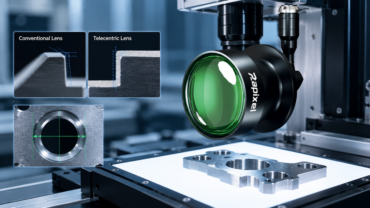
RAPIXEL OPTICAL ENGINEERING GUIDE · PILLAR 4
Telecentric Lens for Precision Measurement: Accuracy, Edge Detection & Metrology
How to build more reliable dimensional inspection systems through stable magnification, controlled imaging geometry, calibrated edge detection, and practical measurement error analysis.
QUICK ENGINEERING ANSWER
Why Use a Telecentric Lens for Precision Measurement?
An object-space telecentric lens helps reduce magnification changes caused by object-height variation. This makes it useful for dimensional measurement, edge positioning, hole inspection, and precision metrology. However, actual measurement accuracy also depends on calibration, distortion, image sampling, illumination, mechanical stability, and measurement algorithms.
In industrial machine vision, detecting a part and measuring a part are two different challenges.
A detection system may only need to determine whether a component is present. A precision measurement system must estimate dimensions consistently, often while parts vary slightly in height, position, orientation, or surface condition.
For applications involving tight tolerances, these variations can influence the measured result even when the camera resolution appears sufficient.
Telecentric imaging helps address one important source of measurement variation: perspective-related changes in image magnification.
This guide explains how telecentric lenses support precision measurement, what determines achievable accuracy, and how engineers can evaluate an imaging system before deploying it on a production line.
1. Why Is Precision Measurement More Difficult Than Visual Inspection?
A machine vision inspection system may produce a sharp image without producing an accurate dimensional measurement.
Measurement results can change because of several interacting factors:
Object Height Variation
Changes in the distance between the object and imaging system may affect apparent dimensions.
Edge Uncertainty
Blur, reflections, illumination gradients, and surface texture can change detected edge positions.
Optical Distortion
Image geometry may vary across the field, creating position-dependent measurement errors.
Mechanical Instability
Vibration, thermal drift, fixture movement, and camera alignment can affect repeatability.
These factors become increasingly important when the required measurement tolerance approaches the uncertainty of the imaging system.
2. How Does a Telecentric Lens Improve Dimensional Measurement?
In a conventional perspective imaging system, the apparent size of an object generally changes as its distance from the camera changes.
For a simplified perspective model, magnification is related to object distance. This creates a potential source of error when measured components have height variation or are not positioned at exactly the same distance from the lens.
An object-space telecentric lens is designed with approximately parallel chief rays in object space, reducing the sensitivity of magnification to object displacement within its specified operating range.
CONVENTIONAL IMAGING
Perspective-Sensitive Magnification
Object distance changes can affect apparent feature size and dimensional calibration.
OBJECT-SPACE TELECENTRIC IMAGING
Reduced Magnification Sensitivity
The optical design helps maintain more consistent magnification across the specified object-space range.
This is especially useful for measuring components with small thickness differences, parts transported on conveyors, and objects positioned within a limited height tolerance.
For a broader explanation of optical geometry, read the Telecentric Lens Fundamentals Guide.
3. Resolution, Accuracy, and Repeatability: What Is the Difference?
These three terms are frequently confused in machine vision metrology.
| Parameter | Meaning | Practical Question |
|---|---|---|
| Resolution | Ability to distinguish spatial details | Can the feature be resolved? |
| Accuracy | Closeness to a reference or true value | How close is the measurement to the reference? |
| Repeatability | Variation under repeated measurements in defined conditions | Does the system return consistent results? |
Why More Camera Pixels Do Not Automatically Mean Better Accuracy
A higher-resolution camera provides more sampling points across the object, but measurement accuracy may still be limited by:
- Lens optical resolution and image contrast
- Residual distortion and calibration quality
- Edge-detection uncertainty
- Illumination stability
- Part positioning and mechanical vibration
- Temperature-dependent system drift
A useful measurement system must combine adequate sampling with controlled optical and mechanical behavior.
4. Telecentric Lenses for Edge Detection and Dimensional Inspection
Many industrial measurements depend on identifying the position of object boundaries.
Typical measurements include:
- Outer diameter and inner diameter
- Hole center position and hole spacing
- Part width, length, and thickness-related profiles
- Pin pitch and connector geometry
- Slot width and edge-to-edge distance
- Mechanical contour and profile verification
Why Edge Quality Matters
A measurement algorithm does not directly observe a perfect geometric boundary. It estimates edge positions from image intensity transitions.
Edge quality depends on image contrast, optical blur, lighting geometry, sensor noise, and the algorithm used.
Telecentric optics help control imaging geometry, while suitable illumination helps produce more stable intensity transitions.
Practical Example: Hole Diameter Inspection
For a precision-machined component, the system may detect the circular edge of a hole, fit a circle to the extracted edge points, and calculate its diameter. The result depends on calibration, optical geometry, edge contrast, and the stability of the edge-fitting algorithm—not just the nominal lens magnification.
Can Subpixel Edge Detection Improve Measurement?
Yes. Subpixel algorithms can estimate edge positions at fractions of a pixel under suitable image conditions. However, subpixel interpolation does not guarantee equivalent absolute measurement accuracy.
Any claimed subpixel performance should be validated using representative parts and calibrated reference standards.
5. Practical Example: Calculating Object-Space Pixel Size
One of the first calculations in a precision measurement project is the physical size represented by each image pixel.
BASIC SAMPLING EQUATION
Object-Space Pixel Size = FOV / Pixel Count
Use the field of view and pixel count along the same sensor axis.
Example: Measuring a 20 mm Field of View
Assume the following hypothetical imaging configuration:
| Horizontal Field of View | 20 mm |
| Horizontal Camera Resolution | 4000 pixels |
| Object-Space Sampling | 0.005 mm/pixel = 5 µm/pixel |
The result means that one horizontal image pixel represents approximately 5 µm in object space under the assumed calibrated geometry.
If an edge-location algorithm demonstrates a repeatability of 0.2 pixel under the tested conditions, its equivalent object-space repeatability contribution would be approximately:
5 µm/pixel × 0.2 pixel = 1 µm
Important: This 1 µm value is an illustrative edge-location repeatability contribution, not a claim of 1 µm absolute measurement accuracy. Other errors and uncertainty sources must still be included.
For example, measuring a width between two independently detected edges requires considering the uncertainty contributions of both edges, as well as calibration and systematic effects.
6. Building a Measurement Error Budget
A reliable metrology system should be evaluated against a defined measurement uncertainty budget.
Relevant contributions may include:
| Error Source | Potential Impact | Control Method |
|---|---|---|
| Magnification variation | Size-dependent bias | Telecentric optics and controlled object height |
| Lens distortion | Position-dependent dimensional error | Optical specification and distortion calibration |
| Edge localization | Boundary-position uncertainty | Lighting optimization and algorithm validation |
| Calibration | Scale and geometric bias | Traceable standards and calibration verification |
| Temperature and vibration | Drift and repeatability loss | Stable mounting and environmental control |
| Part positioning | Tilt, rotation, and measurement variation | Fixture design and geometric compensation |
How Should Uncertainty Contributions Be Combined?
For approximately independent, uncorrelated standard uncertainty components, a simplified combined standard uncertainty model is:
uc = √(u1² + u2² + ... + un²)
This model is appropriate only when the underlying assumptions are satisfied. Correlated contributions, systematic effects, uncertainty distributions, and calibration models may require additional treatment.
For critical dimensional inspection, engineers should validate the complete measurement process using appropriate reference artifacts and a measurement system analysis, such as a suitable Gauge R&R study.
7. Why Lighting Matters in Telecentric Precision Measurement
Even with a suitable telecentric lens, inconsistent illumination can create measurement variation.
The optimal lighting configuration depends on the feature being measured.
Telecentric Backlighting
Useful for silhouette-based measurements of external profiles, holes, pins, and other transmissive inspection geometries.
Coaxial Illumination
Can support inspection of suitable planar surfaces and reflective features when aligned illumination is required.
Diffuse Illumination
Can reduce problematic specular highlights on certain reflective or curved surfaces.
Directional Illumination
Can emphasize selected surface features, but may require careful control of reflection and shadow effects.
For silhouette measurement, the combination of a telecentric imaging lens and appropriately matched collimated or telecentric backlighting can be particularly useful.
However, reflective surface measurements may require a different illumination approach. Engineers should compare actual captured images before selecting a final light source.
For compact AOI architectures, see our related guide: 90° Telecentric Lens + 90° Telecentric Light for AOI.
8. Industrial Applications of Telecentric Precision Measurement
Telecentric imaging is useful wherever dimensional consistency and repeatable image geometry are important.
APPLICATION 01
Precision-Machined Parts
Measure holes, slots, outer dimensions, and mechanical contours for dimensional verification.
APPLICATION 02
Electronic Connectors
Inspect pin pitch, terminal alignment, connector geometry, and small component dimensions.
APPLICATION 03
Semiconductor Components
Support package geometry, component positioning, and suitable high-resolution dimensional inspection tasks.
APPLICATION 04
Medical Device Components
Evaluate selected small-part dimensions and profiles where controlled image geometry is required.
APPLICATION 05
Battery Manufacturing
Inspect suitable tabs, terminals, component outlines, and assembly dimensions.
APPLICATION 06
Automated Production Lines
Enable repeatable non-contact measurement of components moving through controlled inspection stations.
Application suitability should always be confirmed against the required tolerance, object geometry, surface condition, and achievable system uncertainty.
9. Practical Workflow: Designing a Telecentric Measurement System
For engineering teams, the most effective approach is to work backward from the measurement requirement rather than starting with a camera or lens model.
Step 1 — Define the Measurand
Specify the exact dimension, feature, or geometric characteristic to be measured.
Step 2 — Define the Tolerance
Establish the allowable part variation and an appropriate measurement uncertainty target.
Step 3 — Determine the Field of View
Include the complete measurement feature and sufficient margin for positioning variation.
Step 4 — Evaluate Object-Space Sampling
Calculate the physical pixel size and confirm that the smallest relevant feature can be resolved with adequate contrast.
Step 5 — Select the Telecentric Lens
Evaluate magnification, working distance, sensor coverage, telecentricity, distortion, resolution, and depth of field.
Step 6 — Optimize Illumination
Choose lighting that produces stable and repeatable feature boundaries under realistic production conditions.
Step 7 — Calibrate the Imaging System
Use suitable dimensional reference standards to establish scale and correct relevant geometric errors.
Step 8 — Validate Measurement Performance
Test reference parts across the field of view, expected height range, operating temperature, and representative production conditions.
Step 9 — Verify Long-Term Stability
Define calibration checks, maintenance procedures, and monitoring for measurement drift.
For more detail on choosing optical parameters, continue to the Telecentric Lens Selection Guide.
10. When Is a Telecentric Lens Worth Using?
A telecentric lens is especially worth evaluating when the application requires:
- Low sensitivity to small object-height variations
- Stable dimensional imaging geometry
- Repeatable edge and silhouette measurement
- Low-distortion imaging across the required field
- Reliable non-contact dimensional inspection
However, telecentric optics are not automatically necessary for every measurement application.
If the measurement tolerance is relatively loose, object distance is tightly controlled, and a conventional lens can satisfy the validated uncertainty requirement, a conventional machine vision lens may be a practical alternative.
RAPIXEL TELECENTRIC IMAGING
Build a More Reliable Precision Measurement System
Rapixel offers telecentric lens solutions for machine vision, AOI, dimensional inspection, and precision measurement applications.
For a suitable optical configuration, define the object dimensions, measurement tolerance, field of view, camera sensor, working distance, and illumination requirements.
Explore Rapixel Telecentric Lenses →Key Takeaway: Precision Measurement Requires More Than a Precision Lens
A telecentric lens can reduce perspective-related magnification variation and provide a useful optical foundation for dimensional inspection.
But the finished measurement result depends on the entire system:
Telecentric Optics + Camera + Lighting + Calibration + Mechanics + Measurement Software
For precision metrology, the goal is not simply to obtain a sharper image. It is to achieve a measurement process with demonstrated accuracy, repeatability, and stability under real operating conditions.
Frequently Asked Questions
Why are telecentric lenses used for precision measurement?
Object-space telecentric lenses reduce magnification sensitivity to changes in object distance, supporting more consistent image geometry for dimensional measurement within their specified operating range.
Does a telecentric lens guarantee measurement accuracy?
No. Accuracy also depends on lens distortion, calibration, resolution, illumination, edge-detection algorithms, mechanical stability, and environmental conditions.
How do I calculate measurement resolution?
A basic object-space sampling calculation divides the field of view by the number of pixels along the same image axis. For example, 20 mm across 4000 pixels gives 5 µm per pixel. This is a sampling value, not the system's guaranteed measurement accuracy.
Can a telecentric lens achieve subpixel measurement?
Subpixel edge-location algorithms can estimate positions at fractions of a pixel when image quality and contrast are sufficient. Their actual repeatability and accuracy must be experimentally validated.
What lighting is best for telecentric measurement?
Telecentric or collimated backlighting can be effective for silhouette-based dimensional inspection. Reflective surfaces and other features may require coaxial, diffuse, or directional illumination.
What is the difference between telecentricity and distortion?
Telecentricity describes the chief-ray geometry and associated magnification sensitivity to object displacement. Distortion describes geometric deviations in image mapping across the field. Both matter in precision measurement.
How should engineers validate a telecentric measurement system?
Use appropriate calibrated reference artifacts, verify results across the required field and height range, evaluate repeatability and bias, and test under representative operating conditions.
RAPIXEL TELECENTRIC LENS KNOWLEDGE HUB
Continue Exploring Telecentric Imaging
Explore the complete engineering guide, from optical fundamentals and AOI to lens selection, precision metrology, industrial applications, and integrated vision systems.
PILLAR 1
Telecentric Lens Fundamentals
Understand telecentric imaging, perspective effects, and optical geometry.
Read Fundamentals →PILLAR 2
Telecentric Lens for AOI
Explore automated optical inspection for electronics and precision components.
Read AOI Guide →PILLAR 3
Telecentric Lens Selection Guide
Choose magnification, field of view, working distance, and sensor compatibility.
Read Selection Guide →PILLAR 4 · CURRENT ARTICLE
Telecentric Lens for Precision Measurement
Understand dimensional accuracy, edge detection, and metrology uncertainty.
You are herePILLAR 5
Telecentric Lens for Industrial Applications
Explore machine vision applications across semiconductor, electronics, and manufacturing.
Explore Applications →PILLAR 6
Telecentric Vision Systems & Solutions
Integrate cameras, optics, illumination, calibration, and inspection software.
Explore Vision Systems →RELATED AOI ARTICLE
90° Telecentric Lens + Light for AOI
Learn how folded optical paths support space-constrained inspection equipment.
Explore 90° AOI Solution →RAPIXEL PRECISION OPTICS
Looking for a Telecentric Lens for Dimensional Inspection?
Evaluate your measurement tolerance, required field of view, sensor resolution, working distance, object-height variation, and lighting conditions before selecting an optical system.
Explore Rapixel Telecentric Solutions →
Поделиться:
A Practical Selection Guide