

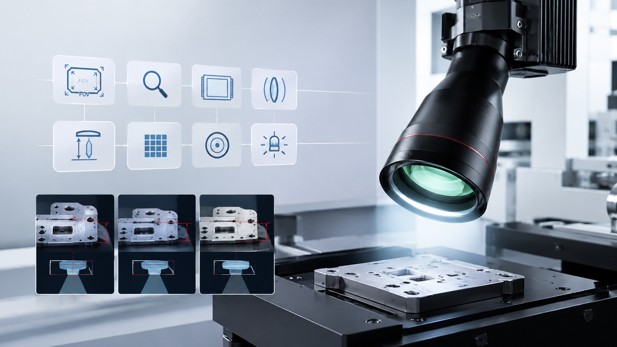
How to Choose a Telecentric Lens: A Practical Selection Guide
A practical guide to selecting telecentric lenses based on field of view, magnification, sensor size, working distance, resolution, telecentricity, depth of field, and machine vision requirements.
Selecting a telecentric lens is not simply a matter of choosing the highest resolution or the largest sensor coverage. The correct optical configuration depends on the relationship between the object, camera sensor, field of view, magnification, working distance, and inspection accuracy.
For machine vision engineers and system integrators, choosing the lens early in the system design can help avoid mismatched components, insufficient field of view, limited working distance, or unnecessary optical costs.
This guide explains the key parameters to consider when selecting a telecentric lens for precision measurement, AOI, dimensional inspection, and industrial machine vision.
1. Start With the Inspection Object
Before selecting a telecentric lens, define the object and the actual inspection requirement. The lens should be selected around what needs to be measured or detected.
- Object size
- Required field of view
- Smallest feature to inspect
- Required measurement accuracy
- Object height variation
- Available installation space
- Object surface and reflectivity
- Required inspection speed
A small mechanical component requiring dimensional measurement may require a very different optical configuration from a large PCB requiring component or edge inspection.
2. Field of View: How Much of the Object Must Be Captured?
Field of View (FOV) is the physical area captured by the imaging system. The FOV should be large enough to contain the complete inspection area while still providing sufficient pixel coverage for the smallest feature of interest.
A practical starting point is:
For example, if an inspection area is 80 mm wide, designing for exactly 80 mm may leave little tolerance for part positioning or fixture variation.
FOV should also account for:
- Part positioning tolerance
- Conveyor movement
- Fixture accuracy
- Multiple objects in one image
- Required inspection region
3. Magnification: Connecting the Object to the Sensor
Magnification describes how the object is represented on the camera sensor. A simplified starting relationship is:
For example, if a camera has a 14.4 mm sensor width and needs to capture a 72 mm object width:
This provides a starting point for lens selection. Actual lens specifications, sensor format, optical design, and usable image circle must also be verified.
Why Magnification Matters
Too low: The inspection feature may occupy too few pixels.
Too high: The required FOV may not fit on the sensor.
For precision inspection, magnification should therefore be considered together with sensor resolution and feature size.
4. Sensor Size and Image Circle
The telecentric lens must adequately cover the camera sensor. Common machine vision sensor formats include:
For line-scan and high-resolution applications, larger image circles may also be required.
A lens designed for a smaller sensor may result in vignetting, insufficient image coverage, or reduced image quality toward the edges.
5. Working Distance: More Than Just Installation Space
Working Distance (WD) describes the specified distance between the lens and the object plane. Working distance is especially important when integrating optics into an automated machine.
Consider working distance together with:
- Mechanical integration
- Lighting placement
- Part accessibility
- Protection from moving components
- Available depth of field
- Overall machine dimensions
A longer working distance can be useful when the object is inside a machine, mechanical components surround the inspection area, or additional space is needed for illumination.
However, longer WD does not automatically mean better optical performance. Working distance should be selected together with magnification, resolution, DOF, and mechanical requirements.
6. Resolution: Match the Lens to the Camera
A high-resolution camera does not automatically produce a high-resolution inspection image. The optical system must be capable of resolving the detail captured by the sensor.
When selecting a telecentric lens, consider:
- Sensor pixel size
- Camera resolution
- Required feature size
- Lens MTF
- Working wavelength
- Magnification
- Object contrast
For high-resolution machine vision systems, the camera and lens should be treated as one imaging system, rather than selected independently.
7. Telecentricity: What Level Do You Actually Need?
Not every application requires the same degree of telecentric performance. For measurement-oriented applications, object-space telecentricity can help reduce changes in apparent size caused by object position along the optical axis.
This becomes particularly useful when:
- Part height varies
- Objects cannot be positioned at exactly the same Z height
- Dimensional measurement is required
- Edge location is critical
- Repeatability is important
Telecentricity should still be considered alongside the actual depth of field and object-space tolerance of the application.
A telecentric lens is not a substitute for proper mechanical positioning or calibration.
8. Depth of Field: How Much Z Variation Can You Accept?
Real production systems rarely have perfectly flat objects positioned at exactly the same height. Parts may have thickness variation, mechanical tolerances, conveyor movement, or fixture variation.
This makes depth of field (DOF) an important selection parameter.
A larger DOF can help maintain acceptable image quality across a range of object positions. However, DOF should not be evaluated independently.
Define the required image quality and measurement tolerance first, then select the optical configuration accordingly.
9. Don't Forget Illumination
Lens selection and lighting design should be considered together. Even a high-performance telecentric lens cannot compensate for inadequate illumination.
Backlighting
Useful for outer dimensions, silhouettes, edge detection, hole diameter, and profile measurement.
Coaxial / Telecentric Illumination
Useful for flat reflective surfaces, precision components, surface features, printed patterns, and electronic components.
Ring Illumination
Useful for general surface inspection, edge features, and components with varied orientations.
Controlled Illumination
Diffusion, polarization, and directional lighting can help manage reflections and improve image consistency.
For some precision applications, a telecentric lens + telecentric illumination configuration can provide more controlled object-plane illumination.
10. A Practical Telecentric Lens Selection Workflow
For system integrators, the following sequence can simplify the optical selection process.
Define the Object
Object size, feature size, surface characteristics.
Define the FOV
Determine the minimum inspection area that must be captured.
Select the Camera
Consider resolution, pixel size, sensor size, interface, and frame rate.
Calculate Magnification
Use sensor size and required FOV as the initial reference.
Define WD
Check mechanical space and lighting requirements.
Check Optics
Evaluate MTF, distortion, telecentricity, DOF, image circle, and wavelength.
Select Lighting
Match lighting geometry to the object surface and inspection feature.
Validate the System
Test the camera, lens, lighting, object, and vision software together.
Telecentric Lens Selection Checklist
| Parameter | What to Define | Why It Matters |
|---|---|---|
| Object Size | Maximum inspection area | Determines required FOV |
| Feature Size | Smallest feature | Determines resolution requirement |
| FOV | Required image area | Determines magnification |
| Sensor Size | Camera sensor format | Determines image coverage |
| Magnification | Required optical scale | Links object size to sensor |
| Working Distance | Available installation space | Affects mechanical integration |
| Telecentricity | Required measurement stability | Reduces perspective-related magnification changes |
| Depth of Field | Object height variation | Determines acceptable Z tolerance |
| Resolution | Required image detail | Must match camera capability |
| Distortion | Measurement requirement | Important for dimensional accuracy |
| Lighting | Object and surface characteristics | Determines image contrast and uniformity |
Common Telecentric Lens Selection Mistakes
A lens should not be selected simply because it matches a camera's sensor size. Required FOV and magnification should be established first.
A longer WD may solve a mechanical problem but may not provide the required magnification, resolution, or depth of field.
Sensor compatibility is necessary, but it does not guarantee that the optical system can resolve the required inspection features.
Reflective, transparent, dark, or highly textured objects may require very different illumination strategies.
Telecentricity and depth of field are different optical properties. Telecentric imaging can reduce perspective-related magnification variation, but the application still requires an appropriate DOF.
Telecentric Lens Selection for Different Applications
Precision Measurement
Prioritize stable magnification, low distortion, suitable resolution, and controlled illumination.
AOI
Prioritize FOV, resolution, inspection speed, optical contrast, and lighting geometry.
Electronic Component Inspection
Consider sensor matching, fine feature resolution, reflection control, and consistent magnification.
Mechanical Part Inspection
Prioritize dimensional accuracy, edge definition, depth of field, and working distance.
Large-Format Inspection
Consider image circle, sensor coverage, optical resolution, and mechanical integration.
How to Select the Right Telecentric Lens for Your System
There is no single "best" telecentric lens for every machine vision application. The correct configuration depends on the relationship between:
For system integrators, defining these parameters before selecting the lens can make optical design more predictable and reduce the risk of component mismatch.
Start With These 5 Numbers
- Object Size
- Required FOV
- Sensor Size
- Working Distance
- Smallest Feature
Need Help Selecting a Telecentric Lens?
Share your object size, FOV, sensor size, working distance, and smallest feature. These parameters provide a strong starting point for evaluating the appropriate telecentric optical configuration.
Explore Rapixel Telecentric Lenses Contact RapixelRapixel Telecentric Lens Knowledge Hub
Understand telecentric imaging, perspective effects, and why telecentric optics are used in machine vision.
Read Pillar 1 →
Explore how telecentric optics support automated optical inspection and precision defect detection.
Read Pillar 2 →
You are here.
Learn how telecentric optics fit dimensional measurement applications.
Read Pillar 4 →
Explore telecentric imaging across different industrial inspection scenarios.
Read Pillar 5 →
Understand how camera, lens, illumination, and vision software work together.
Read Pillar 6 →
See how a 90° optical path can help integrate telecentric imaging into space-constrained AOI systems.
Explore the 90° AOI Solution →
Share:
لماذا تحتاج إلى عدسة تيلسنتريكية بزاوية 90° وإضاءة لـ AOI